RSU Setup
This section introduces the fundamental software concepts associated with setting up a RSU. For important issues relating to physically installing a RSU, refer to the Roadside Unit Operator Guide for the corresponding model of RSU.
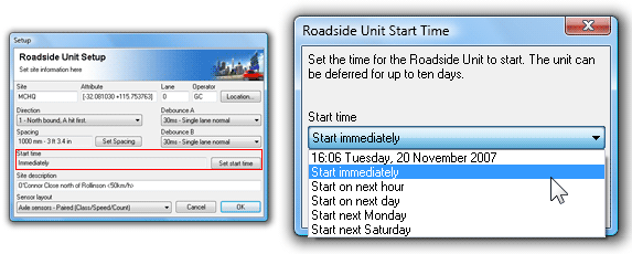
Starting a RSU is an extremely simple process of describing the site via a set of setup parameters, and specifying a start time. For the most part, the setup parameters are purely descriptive, and do not affect RSU operation. The RSU continues logging until stopped, or filled to capacity.
For simple, infrequent surveys, RSUs can be easily configured on site. For planned surveys, Site Lists simplify the process even further, and minimize user error.
The Site parameter is user-defined and may be up to 20 characters long. This is commonly used to represent the name or serial number assigned to the site where the RSU is placed.
The Site parameter is used as the first part of a dataset's filename when unloading data.
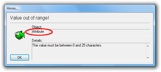
The Attribute parameter is user-defined and may be up to 25 characters long. This is commonly use for site coordinates, or sub-grouping sites, for example by suburb or county. The Attribute parameter can be optionally used for grouping datasets into different folders when unloading data.
The Operator parameter is the initials (up to three characters) of the RSU operator's name. This is useful for identifying field operators if they need to be asked about a particular survey.
A RSU becomes active once it is setup, however the logging of sensor hits can be deferred for up to 10 days. This feature is useful for conserving memory by only logging during the specific period of interest. It is also useful when a RSU is to be setup in the office and placed in the field some time later.
Note that a survey end time is not specified. The finish time of the data is set at the point the RSU is unloaded and/or stopped. MCReport provides tools for selecting a report's period from the available data.
The default setting is to start logging immediately. To defer logging, any time in the next 10 days can be manually specified, or several automatically calculated boundaries are provided.
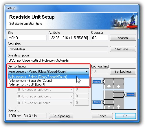
A RSU can be installed using a variety of Sensor Layouts, to obtain either classification data using a pair of sensors, or event-count data from a single sensor. The Sensor Layout describes the configuration of the sensors for use by MCReport during analysis - it does not affect the operation of the RSU. The options for Sensor Layout will change depending on the model of RSU connected.
![[Note]](MTEHelp/images/note.png)
|
Note |
|---|---|
| For Sensor Layout recommendations and limitations, refer to the Roadside Unit Operator Guide for the model of RSU. | |
Axle Sensors - Paired, also referred to as a Classifier Layout requires a pair of parallel axle sensors (tube/hose or piezo sensors) spaced a known distance apart. This is the most commonly used sensor layout as it gives the best value-for-effort in terms of the wealth of information that can be obtained from the raw data. MCReport partitions the raw hits into vehicles, and calculates vehicle class, speed, direction, headway and so on.
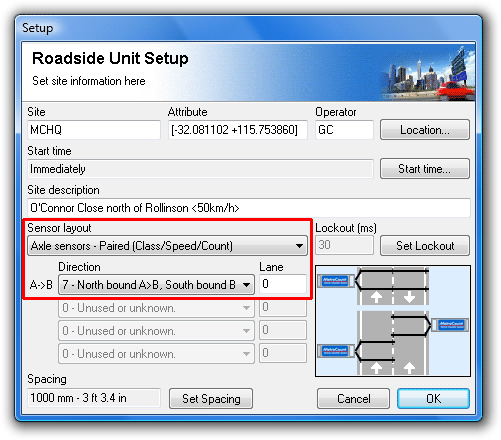
This Sensor Layout provides one Direction option (either unidirectional or bidirectional) and one Lane designator. The Spacing between the sensors must also be specified.
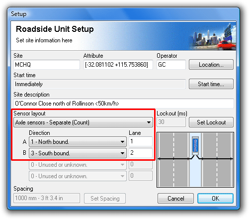
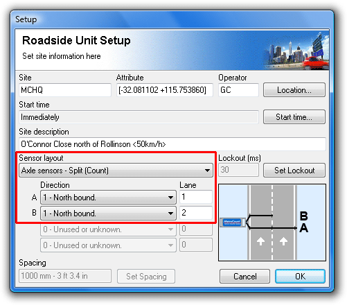
The Separate and Split layouts can be used to obtain short-term counts of raw hits or events, but not classified vehicles. These layouts are useful for sites where a Classifier Layout is inappropriate, such as multiple lanes with traffic flows in the same direction.
A Separate layout indicates the event counts on each sensor bear no relationship, such as being on opposing carriage-ways.
A Split layout can be used to differentiate event counts across a pair of lanes. Using a pair of sensors (one long and one short), the short sensor gives one lane, and the long minus the short gives the other lane. Using additional RSUs, this method can be extended to more than two lanes.
When selecting either of these layouts, a Direction and Lane number are available for both inputs.
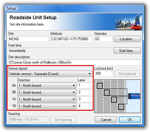
The Site Description parameter may be up to 70 characters long. It is used to identify a survey site. It is useful to settle on a convention, such as the road name and nearby intersecting roads, landmarks or sign posts.
A site's posted speed limit (PSL) can also be entered into this field. MCReport will optionally scan for a speed limit in the following form:
- Must be enclosed in angle brackets < >
- Default is km/h. Append an 'm' or 'M' for mph.
- The speed limit can appear anywhere in the description, but other angle brackets cannot be inserted when using this feature.
The Direction parameter specifies the approximate direction vehicles at the site are headed, or the overriding direction of a carriageway of a freeway or highway. Direction is specified as north, south, east or west bound, so it is simply a matter of selecting the compass point that best approximates the actual direction of travel.
For a Classifier Layout (pair of sensors), the direction a vehicle was travelling is determined by the sensor that was hit first. Vehicles travelling from A to B is known as the primary direction, and vehicles travelling from B to A is called the secondary direction.
There are eight direction codes to choose from. The first four are for single lane sites, and only the primary (A>B) direction is specified. The second four direction codes are for bidirectional sites, and both the primary (A>B) and secondary (B>A) directions are specified.
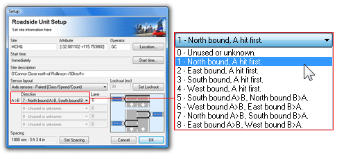
Remember that the direction code is a purely descriptive field, for reference during data analysis. For single lane sites, vehicles travelling in the secondary direction (for example, overtaking) will still be logged. The RSU does not filter vehicles.
When using a Count Layout, the analysis software has no concept of vehicles, so the concept of A>B and B>A is dropped. A second direction code is provided for Separate mode, when the A and B sensors can be placed independently.
The lane number is used to distinguish data collected from multiple lanes at one site. By convention, a lane number of zero (0) is used for single-lane or bidirectional sites.
For multi-lane sites where multiple RSUs are required, each should be setup with a unique lane number starting at 1, through to a maximum of 15. When data is unloaded, the lane number is included in the file extension of the suggested dataset name. For example, the files for a multi-lane site with two RSUs can be easily recognised as having the same file name with .ec1 and .ec2 file extensions respectively.
A consistent numbering convention will help differentiate datasets. For example, number the lanes consecutively, start at one (1) from the west (north-south roads), or north (east-west roads).
For RSUs with axle-sensors, the Lockout time is used to eliminate spurious, closely-spaced sensor hits, primarily to avoid wasting data storage space. Extra hits that are actually logged will be filtered out by the data analysis software.
The Lockout setting specifies the time period (in milliseconds) after a logged sensor hit, for which further sensor hits will be rejected. The recommended Lockout setting are:
- 10ms if the sensor spans multiple lanes, and
- 30ms if the sensor spans a single lane.
For RSUs with loop sensors, the Lockout time is used to eliminate multiple counts for long vehicles where the loop may "untrigger" mid-vehicle. The default setting is 350 milliseconds.
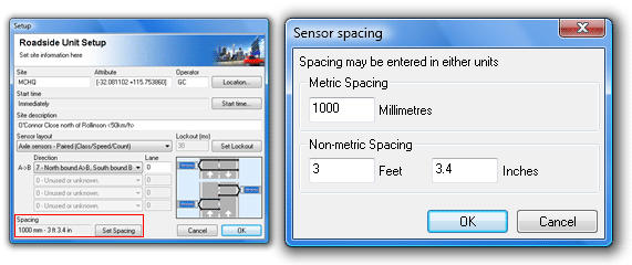
The Spacing parameter specifies the distance between the sensors when using a pair of sensors in a Classifier Layout. This parameter is disabled when using a Count Layout.
MCReport is optimised for a spacing of one metre (three to four feet). A longer spacing of up to three metres (or 10 feet) can be used for improved speed accuracy.
The spacing is stored by the RSU in millimetres. During setup, the spacing can be entered in either metric or non-metric units.
MCSetup provides the option to store a site's coordinates (latitude and longitude) in the Attribute field. Coordinates can be entered manually, or read from any serial GPS unit that supports the NMEA 0183 data format. The serial port used by the GPS unit is set in MCSetup's Preferences. USB and Bluetooth GPS devices usually create a virtual serial port that can be used by MCSetup, provided other GPS software it not using the port.
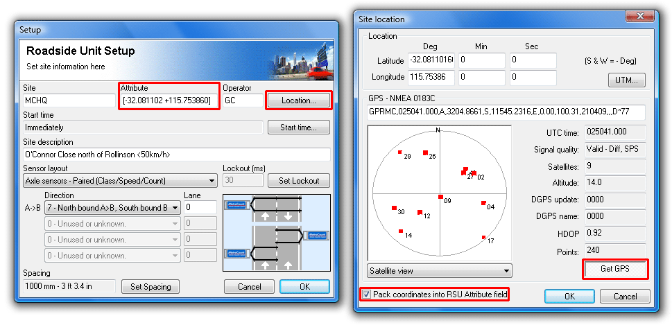
MCSetup's GPS interface is accessed via the Location button in the Setup dialog box. The Get GPS button at the bottom will start taking continuous readings.
A setup operation transfers a new set of setup parameters into the RSU's header, and sets the RSU active, effectively erasing the previous set of data.
|
|
Note |
|---|---|
| A data protection feature prevents a RSU from being setup if the RSU has not been stopped using the normal unload procedure. If the RSU's data is not required, its status can be quickly cleared by performing a Factory Setup. | |
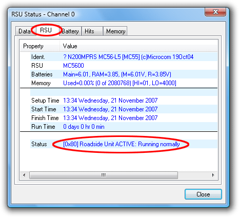
It is good practice to check a RSU's status before and after a setup. Before, to check the unit is successfully communicating, and a final check of battery levels. After, to verify the setup was successful, and the RSU is active.
When performing a setup, the initial setup values are taken from the RSU's current header. This feature is useful when a RSU is close to or has reached full capacity, and further data is required from the same site. After the existing data has been unloaded and the RSU stopped, restarting the RSU does not require the setup parameters to be re-entered. Multiple datasets from the same site can be easily combined into a single report in MCReport.
|
|
Note |
|---|---|
| RSU's do not have a real-time clock. The PC's time is stored in the RSU's header at setup, and the time-stamped hits are referenced from this time. Remember to check the PC's time regularly! | |
![[Procedure]](MTEHelp/images/procedure.png)
|
To setup a RSU |
|---|---|
|
|